
The tower was constructed in the fall of 2017. It was lowered about 2019 to repair the Cushcraft A3S 20-15-10 trap beam after the center insulator broke due to high winds. I found there was a heavy duty version of the center insulator available which was intended to be used when adding a 40 meter dipole kit, but it works fine with the standalone 3AS and makes it much more robust in high winds.
The tower was lowered again in 2025 to remove the A3S and replace it with an OB7-3 which has much wider bandwidth on 20 meters due to full-sized elements and does not have any traps which might fail.
And the tower was lowered again in 2026 to replace the failed top of tower thrust bearing and to replace the 6 meter failed coax. Details on the initial tower construction in 2017 follow, and then details on the thrust bearing replacement in 2026 are included.

Placing the rebar cage into the 5′ x 5′ x 5′ base hole using a boom on the front-end loader

KA2C (Nelson Sollenberger) wiring the rebar to the tower base and adding stabilization wires

Pouring about 7 yards of concrete with the tower base and first 10 foot tower section in place

A tower MUST be adjusted for perfect level before and during the concrete pour – Two large carpenter levels placed at 90 degrees were used for precise leveling for this tower

The Universal 40 foot fold-over tower with Ham IV rotator and 16 foot mast, antennas and coax feed lines ready for raising

Raising the tower with friends lifting on each of 2 attached legs and a winch from the truck connected via a pulley on a fence post to a point on the 3rd leg at about the 25 foot point on that leg – The fence post is braced to 2 other fence posts

Each tower leg is connected to a dedicated ground rod and a dedicated buried #6 solid copper ground wire – An aluminum clamp connects to each tower leg which is also aluminum and stainless steel sheeting isolates the aluminum clamps from the copper ground wires – All tower leg ground rods are bonded together with ground wire circling the tower base – The tower leg closest to the shack bonds to a similar ground system for the shack.

Plowing in ditches for ground wires for each tower leg

Using the Ford and 3-point hitch blade to fill in the ground wire ditches
In 2026, the thrust bearing at the top of the tower froze and had to be replaced. Also, the coax to the 6 meter 3 element Yagi failed, probably due to water penetration. After lowering the tower and removing the antennas, then the mast and finally the thrust bearing. It looked like this after almost 9 years:
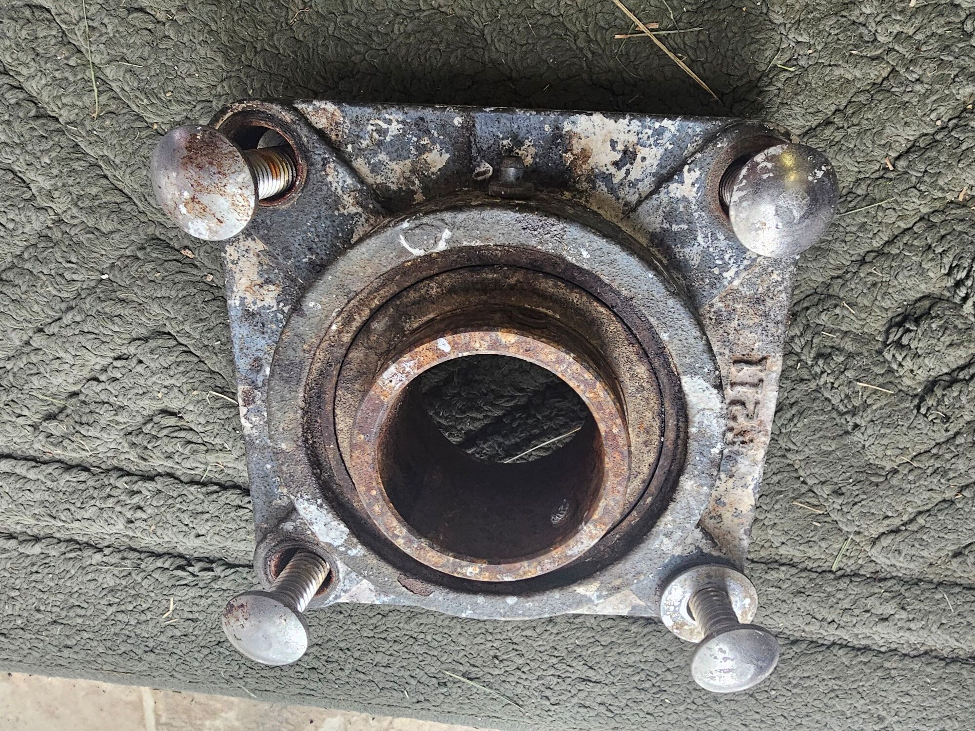
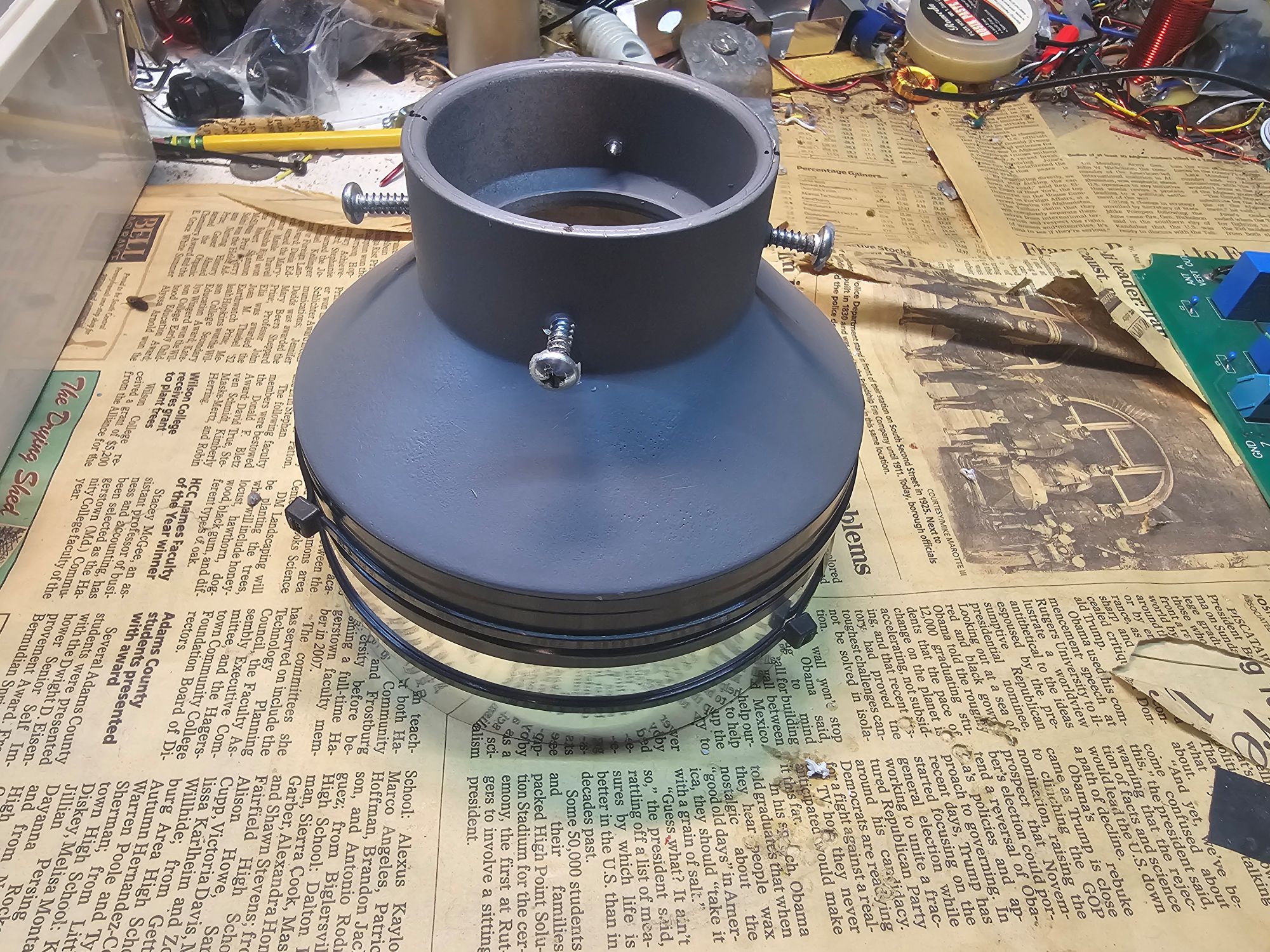
It was degraded from bird droppings as well as rain water. A bit of research showed that actually it is an open general purpose bearing and there is a grease fitting to grease it every 6 to 12 months. Of course at the top of the tower that does not happen. Bird droppings and rain water can easily work into the crack between the fixed and moving collar. It did well to last almost a decade. After some discussion with Jeff Addleman, W3ADD, I decided to replace the bearing with a new one and to construct a shield using a PVC 2″ to 4″ adapter. First the adapter was painted gray for protection from the sun; then 4 set screws were added; and finally a ring of aluminum flashing was added at the base on the 4″ side to cover the fixed collar of the thrust bearing. Once the collar was installed on the mast just above the thrust bearing to protect the opening to the thrust bearing ball bearings, silicone was added to fill the narrow space between the PVC adapter and the 2 inch aluminum mast around the 4 set screws.
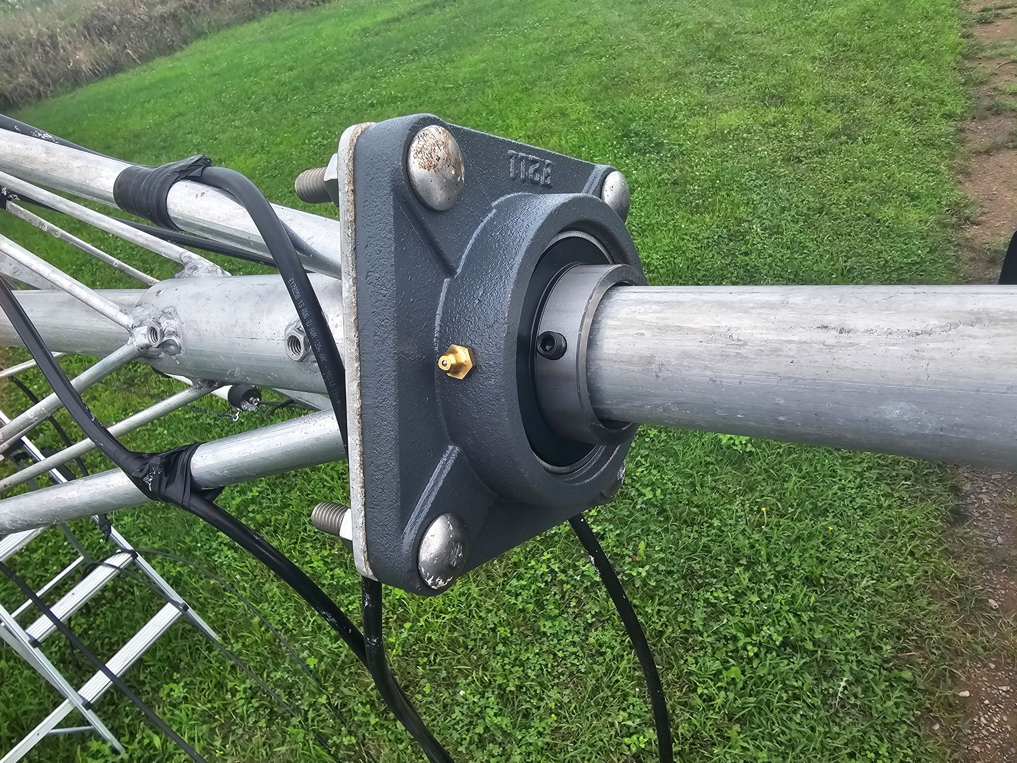
The new thrust bearing was installed at the top of the tower and then the mast reinstalled:
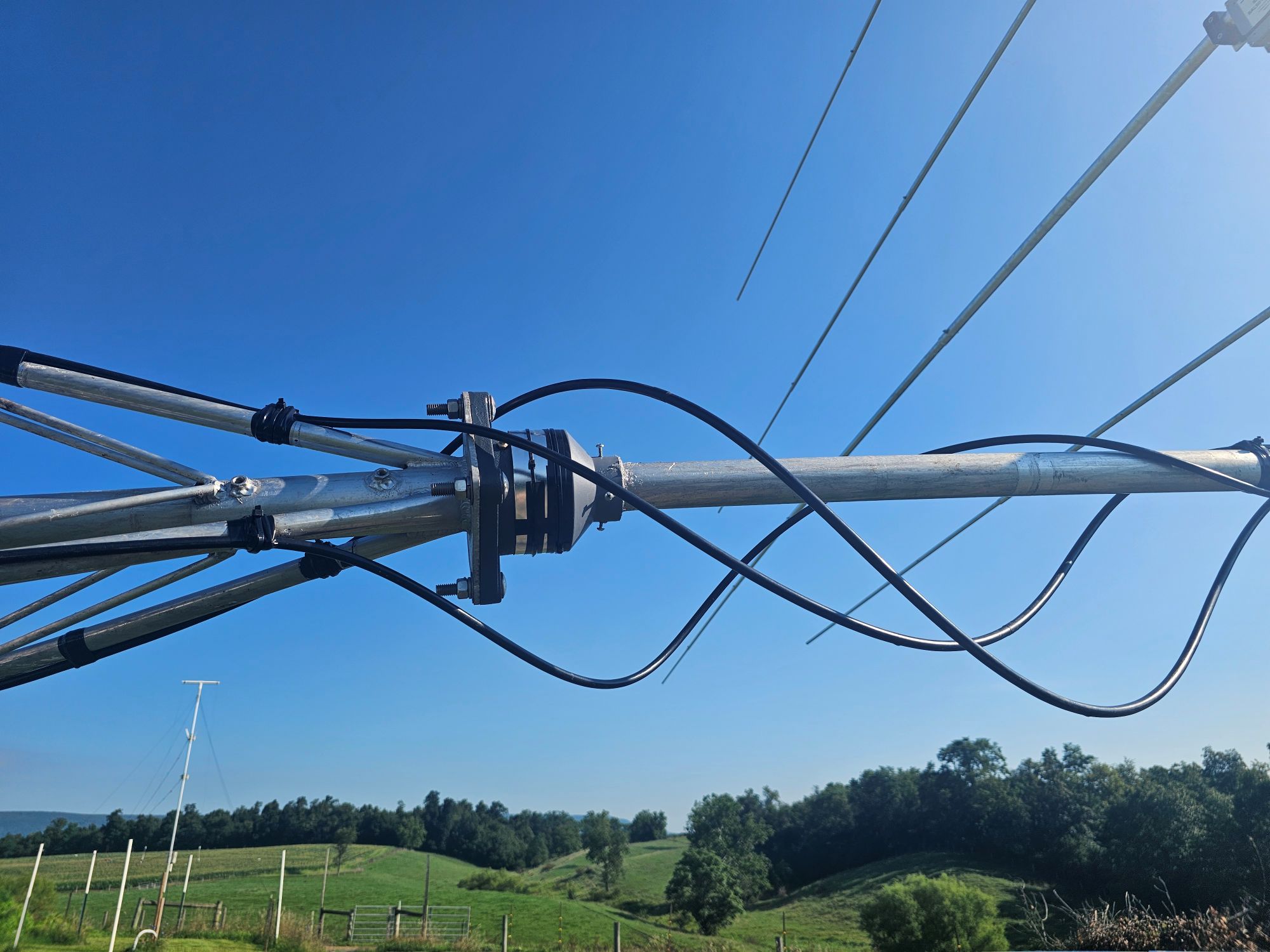
Next the thrust bearing shield was installed and silicone added in several applications around the 4 set screws to block rain and droppings. Then the antennas and coaxes. There are 3 buryflex coaxes going up the tower: the 3-band Optibeam OB7-3 for 20-15-10; the 6 meter beam; and the 2 meter and 70 cm beam. They were positioned and secured with slack using electrical tape and tie wraps to allow full 360 degree rotation of the mast and antennas without binding and with margin.
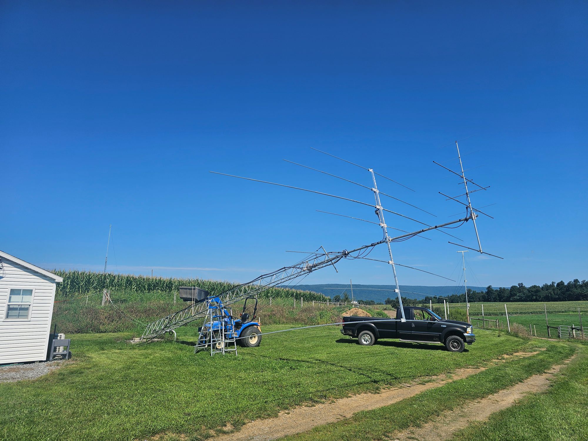
After redressing the cables down the tower and testing of all the antennas and the rotator, it was finally time to raise the antenna back to its vertical position. The tower was down for the replacement of the thrust bearing and the 6 meter coax and maintenance for about 8 days. Several friends assisted during the lowering of the tower and removal of the antennas, and several others helped to reinstall the large OB7-3. But I was able to raise the tower almost entirely alone using a front-end loader New Holland tractor and a rear mounted winch on the farm truck. The front-end loader was used to perform 3 or 4 lifts with supporting step ladders moved closer to the tower base with each lift and with the tower raising a bit with each lift. A winch connected to a cable going to a post on the cow walk and then to a point about 30 feet up the tower. Then the winch was engaged alternating with the front-end loader for several lifts until the winch was able to lift the tower alone. With the tower finally at a vertical position, W3ADD assisted to reinstall the base bolts. Especially installing the first bolt at the tower base that was removed to lower the tower is difficult since the tower must be moved back and forth slightly to reach alignment.
Once the tower was fully setup, the rotator and antennas were retested and all was good. Getting back on the air with everything working was FB (Fine Business).