
Antenna setups for ARRL Field Day in June each year and Winter Field Day in January will depend on many issues and factors for individuals, contest groups and clubs. These issues and factors include: 1) size of effort, number of rigs and club size; 2) focus of a club or contest group on EmComm, contesting, social gathering or other things; 3) site for the Field Day; 4) available equipment; 5) location in the USA (coastal, inland,…) and elsewhere; 5) operating modes; 6) experience and knowledge of the club with different antennas; and others. The number of rigs plays a significant role.
Many of the antennas discussed here are commercial off-the-shelf products, especially for 20-15-10 meter antennas, but some are homebrew and are mostly 80 and 40 meter wire antennas. Four key issues play a role: 1) suitability for good antenna isolation to manage inter-station same-band interference using cross-polarization and end-to-end dipole nulls; 2) multiband support in 20-15-10 and 80-40 arrangements to support triplexer/diplexer and filter systems to share coaxes and antennas for multiple rigs; 3) suitability for field operation with easy setup and teardown; and 4) minimal usage of towers and supports.
Many efforts are a single ham or several hams only. Home setups are common, but of course the antennas then are conventional home QTH antennas. Some efforts may be similar to a one-person POTA operation and may have small lightweight antennas with only one or a limited number of antennas and a single rig. Wire antennas such as EFHW, fan dipoles, G5RV and others that can be supported by trees or simple supports are attractive for 1 rig setups in the field. But also a number of manufacturers make portable antennas that may be attractive with different arrangements including Buddipole, Radioddity, Chelegance, Chameleon, and others.
A mid-range club effort for Field Day may have 2 to 6 rigs, and most clubs operate in this range. Less than 50 clubs have Field Day efforts with 7 to 9 rigs, and only about 10 clubs have 10 or more rigs in recent years as of 2026. Antenna setups, planning and overall effort for operations with 10 or more rigs are in a class of their own, and 7 to 9 is still very substantial. The discussions that follow and the antennas included are intended primarily for operations with 2 to 6 rigs although much of the information is more broadly useful.
For planning any multi-rig setup for Field Day that involves same-band operation with multiple antennas on the same band, it is HIGHLY recommended to either model the multiple antennas together with EZNEC to estimate the isolation or to use known setups with possible carefully considered extensions and/or modifications. In any case, actual measurements in the field using a spectrum analyzer (tinySA is a good choice for this) or possibly an oscilloscope with bandpass filters is also recommended. To model isolation, load two antennas under consideration into EZNEC appropriately oriented and spaced. Replace the source in the victim antenna with a 50 Ohm load. Look at Src Dat at the desired frequency. Then examine the currents in the active antenna and in the victim antenna at the source and at the 50 Ohm load. The ratio of the currents is the isolation (20xlog (ratio of currents) for dB of isolation). There can be major surprises with antenna isolation results compared to expectations or intuition. For example, an antenna setup that may appear by intuition to have good cross-polarization isolation may in fact provide poor isolation. On the other hand, some setups may support very good isolation that are not particularly obvious such as a vertical several hundred feet off the center of an inverted vee.
In 2018, our club, the ARA (Antietam Radio Association) experienced crippling interference between our digital and CW rigs as well as significant problems for the 4 phone rigs operating class 6A. A post mortem quickly revealed that one major problem was using vertical antennas on both digital and CW, sometimes on the same band, separated by about 300 feet (planning had some limitations). The isolation between the 2 verticals was less than 30 dB on 40 meters since 2 verticals are operating broadside to each other, so each receiver was badly overloaded when the other setup was transmitting. A key issue was simply good coordination and planning, but the ARA also resolved to make clean and efficient operations at Field Day a priority. A number of results came out of the efforts that followed making Field Day operations much cleaner and effective with different interference issues addressed over the following few years. One of the results was the planning, construction, testing and usage of a number of antennas appropriate for Field Day for mid-sized club efforts with 2 to 6 rigs. We also investigated antenna supports and other equipment for Field Day associated with the antennas. Those antennas, alternative antennas, and associated equipment are a part of the following:
Triplexer Filter Systems
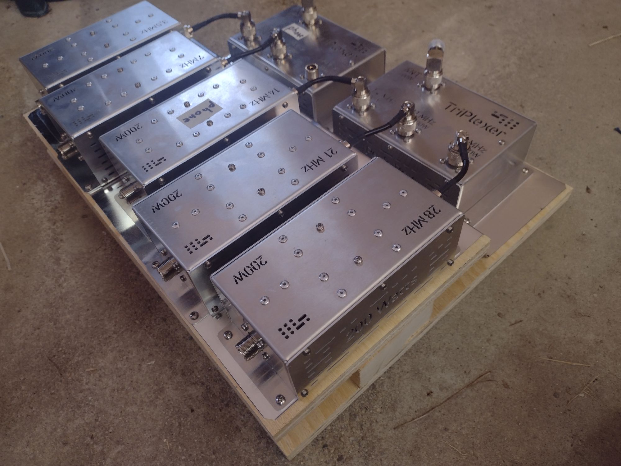
This is a picture of a Triplexer/Filter System (TFS) using Low Band Systems equipment. The ARA has 2 such setups. They cover 80-40 (20) and 20-15-10 in a single piece of equipment. There is an 80-40-20 triplexer (20 meters is typically unused on this triplexer) and an 20-15-10 triplexer and filters for the 5 bands. Two levels of wood base are used to make the triplexer to filter connections most convenient and very short. And a sheet of aluminum underneath all of the filters and the triplexers ensures excellent ground bonding for the TFS’s. For several years, the ARA would setup and teardown the individual boxes and coaxes for each Field Day. This took time and also exposed the setup to possible failures due to manipulating the connecting coaxes. With the construction of the complete TFS’s, setup and teardown are noticeably faster and less prone to problems. A TFS is placed in a convenient location close to a cluster of rigs; one coax runs to a multiband 20-15-10 antenna and another coax runs to a multiband 80-40 antenna. Up to 5 rigs, one on each band from 80 to 10, can operate in parallel with each running a 10 to 25 feet coax to the TFS. Typically we have 2 or 3 rigs on an antenna cluster covering 80 to 10 meters. To change bands for a rig, you move the rig’s connecting coax to the appropriate TFS bandpass filter output which is about a 1 minute operation. You can change bands for one rig while another rig continues to operate as long as the band in use by the active rig is not involved (DO CHECK the coaxes & operators to avoid a hot switch). Within a cluster, no same-band operations is allowed between rigs. All rigs in a cluster must be on different bands, but they can be different modes. Between clusters, strong antenna isolation is designed using spacing, cross-polarized antennas and other techniques, and same-band operations is possible.
TFS’s have been available now for around 15 years. In June, 2010. QST included an article by K6KV, Gary Gordon, entitled “HF Yagi Triplexer Especially for Field Day.” A key advantage is sharing coaxes and antennas across 2 or 3 simultaneous operating rigs. If operating power is limited to 100 Watts per rig, a TFS is modest in size and easily setup for Field Day. They inherently include high performance bandpass filters which is a key item to mitigate Field Day interference when operating a number of rigs. Their usage is most suitable for mid-sized operations with 2 to 6 rigs total. They are generally unnecessary for single rig operations. For large operations with many rigs, large clubs may use single band antennas for best performance. Bandpass filters are then very important, but triplexers are not needed. TFS usage fits well with multi-band antennas, especially 20-15-10 meter Yagi’s, but they also fit well with 80-40-(20) meter antennas. The ARA may use 100 to 150 feet of coax to reach an 80/40 meter antenna, so using a single coax is very convenient. A good TFS is not inexpensive and homebrew systems are not recommended except for highly skilled hams. A TFS as shown or a similar system may cost around $2000. Once the number of RF inductors and RF capacitors involved is counted and the need for precision is considered, the cost is more clearly justified. However, the cost of a complete system as shown is in the range of 1 good rig or a bit more.
A TFS should NOT be used with a non-resonant antenna with high SWR. Operation above 3 to 1 should be completely avoided, and preferably SWR is kept below 2 to 1. High SWR operation may result in high RF voltages that can damage components, especially if capacitor voltage ratings are exceeded. High SWR operation can also cause overheating. It is recommended to always sweep antennas with a TFS or bandpass filters using a nanoVNA or SWR meter prior to attempting operation with a rig. It is good practice to note & display the exact frequencies that should be used for operation. If an antenna is tuned for CW, but you intend to use it instead for phone, retune the antenna prior to operations.
Dunestar manufactured TFS equipment starting soon after the K6KV QST article, but they shut down in 2023. VA6AM makes Triplexers and Bandpass Filters (sold through DX Engineering) that are used successfully by many hams. The series rated for 200 Watts is appropriate for Field Day with 100 Watt rigs. VA6AM also makes high power systems. 4O3A makes high power systems, but these are not appropriate for most Field Day operations due to size and cost associated with high power requirements. Low Band Systems also makes quality equipment for TFS’s, and ARA uses their equipment. Unfortunately access and availability has been complicated by the Russia-Ukraine war the last few years, but direct purchasing appears possible.
The usage of these TFS’s are synergistic with most of the antennas used by the ARA for Field Day. And most antennas are multi-band organized as 20-15-10 or 80-40 systems, but the usage of such multiband antennas is convenient with or without TFS’s for mid-sized FD operations.
20-15-10 Antennas
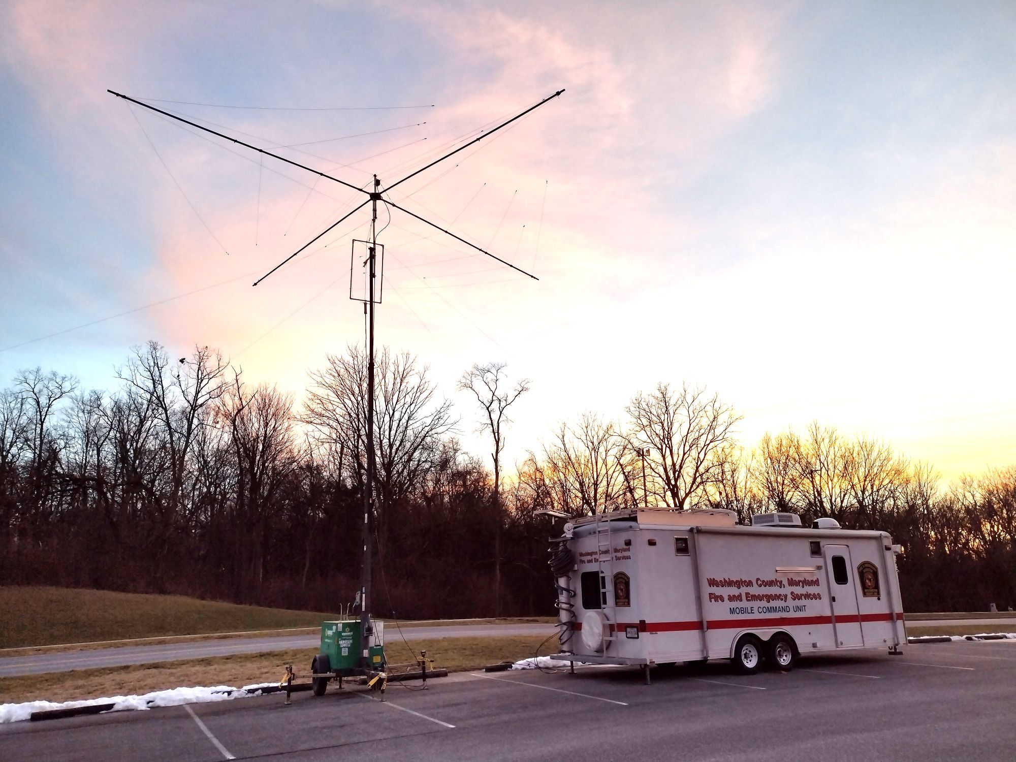
A 20-15-10 spiderbeam is shown mounted at about 35 feet on a light tower. The lights were removed from the light tower. Below the spiderbeam an 80-40 wide-spaced inverted vee is setup. A center unit for the 80-40 inverted vee uses a PVC pipe spacer to separate the wires at the feed point where a BALUN is seen at the bottom. This was used for Winter Field Day 2024 by the ARA. Inside the EmComm trailer, 2 rigs were setup with a TFS connecting to the 2 antennas.
The July, 2026, QST included an article by NY9D, Erico Westgard entitled “Converting Retired Construction Light Tower Trailers for Radio Use”. Light Towers are especially convenient for Field Day and other events to support 20-15-10 Yagi’s and inverted vees for 80/40. ARA members own two modified Generac MLT3060K light towers. These light towers provide the highest available towers at about 30 feet for conventional light towers, and they include the important feature to lower the tower to a horizontal position for easy ground level antenna installation. They are entirely self supporting including outriggers and can be used in a parking lot (they are best used in a parking lot for stability). They raise quickly with manual winches for tower extension and for raising the tower from horizontal to vertical, and they can even be raised by a single ham. They support manual rotation of the tower at the base. A light tower can be towed to the site by an SUV or small pickup truck since they weigh only about 1800 pounds. The generator can provide 6 kW continuously and 8 kW peak power. A 30 gallon diesel tank supports 48 hours of continuous run time. The ARA uses the light tower generator only for backup since we have quieter generators and more efficient generator/inverters available, but the light tower generator is a valuable capability. The light towers double as backup home and radio shack generators for their owners. The 4 large lights were removed, and the 220 VAC 30 amps outlet was modified to support 220/110 VAC at 30 amps using a NEMA L14-30R locking receptacle, and then hardware acquired to mount a 10 feet steel pipe mast on the tower with clamps and wooden spacers. Used MLT3060K light towers are available on www.ironplanet.com. Ironplanet does provide good detail online about a unit’s condition. Working units in good condition usually sell for $1000 to $1600 (this is 10 cents on the dollar compared to new units). However they may be a 100’s of miles away and need to be shipped. We have found light towers to support very rapid and convenient setup and teardown since they are simply towed into position. They deploy in a small space at the edge of a parking lot. A variety of mid-sized antennas, including Yagi’s, rotating dipoles and inverted vees can be supported up to about 35 feet with a 10 feet mast at the top of the tower.
Commercial portable towers on trailers are available for cellular base station, emergency, temporary and other applications, but they are expensive. Also the usage of lifts is now very common in construction and repair businesses and can make excellent temporary supports for ham antennas. Pneumatic masts are sometimes used for remote to TV studio links and other portable wireless applications. If there is access to any of these options, they can be great antenna supports.
Hams have also often used ordinary 10 feet sections of 25G 3-leg tower to raise 20 to 50 feet temporary Field Day towers with the help of a number of hams to raise them manually and secure them with multiple groups of guy ropes. Surplus military developed portable antenna mast systems can be excellent options. The 50 feet AB577 is a popular choice. However it weighs several hundred pounds and requires guy ropes. These options can give great results for Field Day antennas, but generally require significantly more effort than towers on trailers.
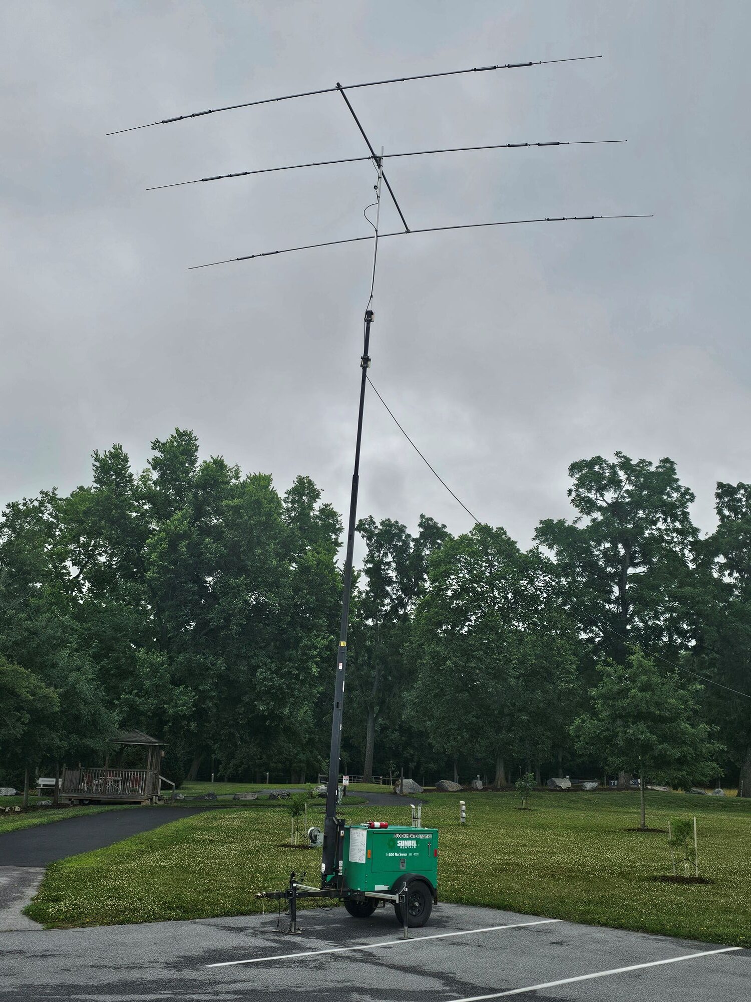
A Cushcraft A3S 20-15-10 Yagi is shown mounted on a light tower. This was first used at 2026 Field Day. The spiderbeam gave excellent performance, but the setup and teardown takes as much as 2 hours each due to the many wires and pieces, and the need to carefully sort through the pieces and assemble and store them with care.
The A3S provides similar performance, and setup and teardown is perhaps 30 to 45 minutes. The antenna is broken down into the boom of length 14 feet, and then the 3 elements are each broken into a small bundle of 4 or 5 lengths which go together quickly with the hose clamps. The antenna tubes are conveniently latched on top of the lowered light tower beside the collapsed tower for transport. A Mosley TA-33-jr is an alternative. Mosley also makes trap-based rotatable dipoles and 2-element Yagi’s which should support fast setup and teardown and work well with a TFS.
Hexbeams covering 20-15-10 are popular for portable operations and can work with a TFS. These provide 2 folded or curved elements (a driver and a reflector) and could be a good choice for 20-15-10 with a light tower; pushup mast with guy ropes; or other portable towers and masts. They are very compact, and some claim that setup can be in as little as 20 minutes. WIMO sells a folding Hexbeam that can be setup in as little as 10 minutes. More info including an EZNEC model can be found here: http://www.karinya.net/g3txq/hexbeam/eznec2/
A number of 20-15-10 trapless Yagi’s are now available. They can provide performance improvements over trap based Yagi’s such as wider bandwidth and they avoid any issues with trap failures. However, they also have many more elements which makes assembly and teardown more complicated. They probably are good choices for fixed home QTH installations, but are less attractive for portable usage due to the many elements for tribanders.
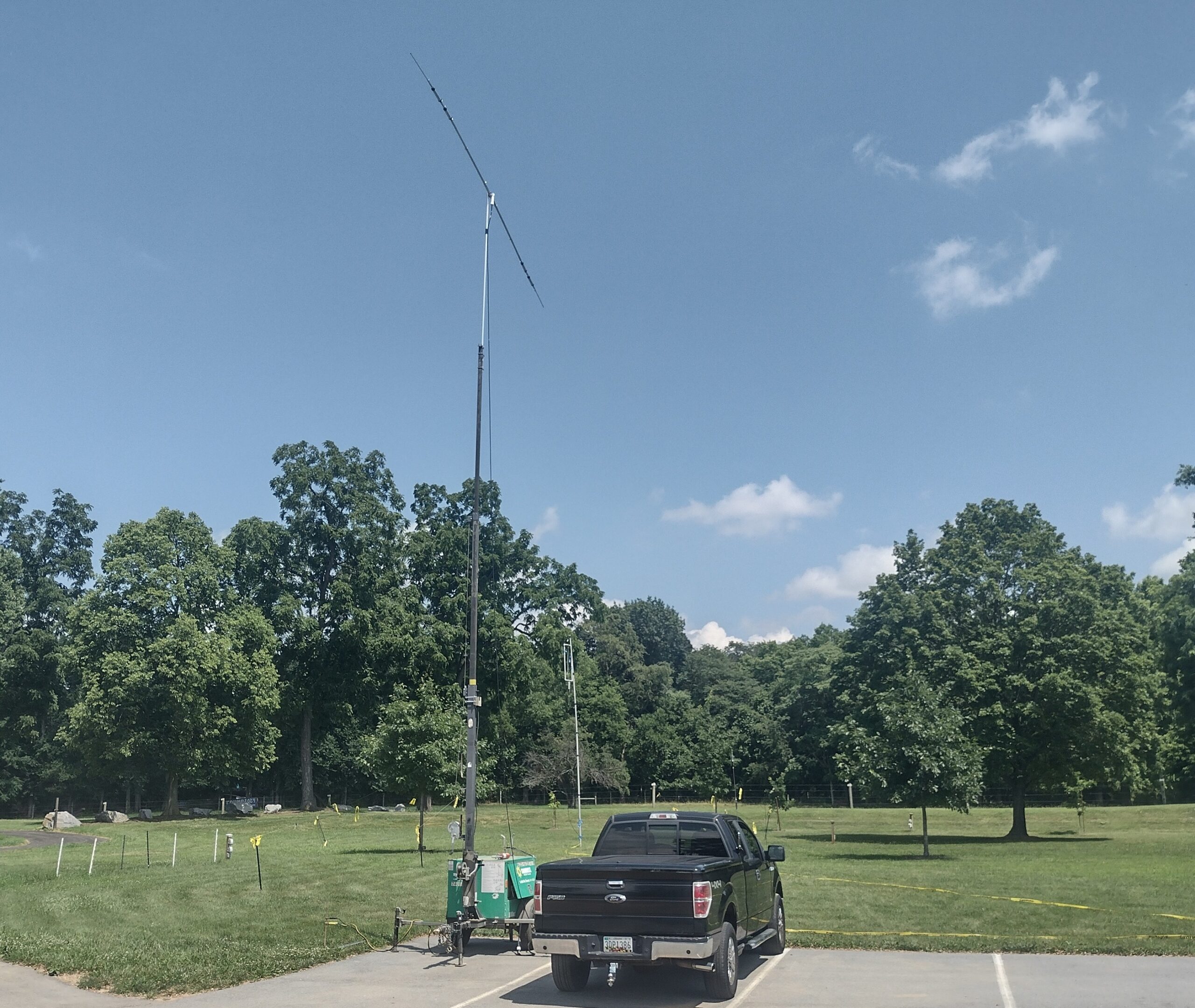
At Field Day 2025, the ARA used a Cushcraft D3 rotatable trap dipole for 20-15-10. This antenna can setup and teardown in only 15 to 30 minutes, and it stores in about 5 pieces. compared to a wire based dipole, it can be setup with a single support and of course it can be rotated to favor a dominant direction. There are other 20-15-10 rotatable dipoles such as the Diex DXS1
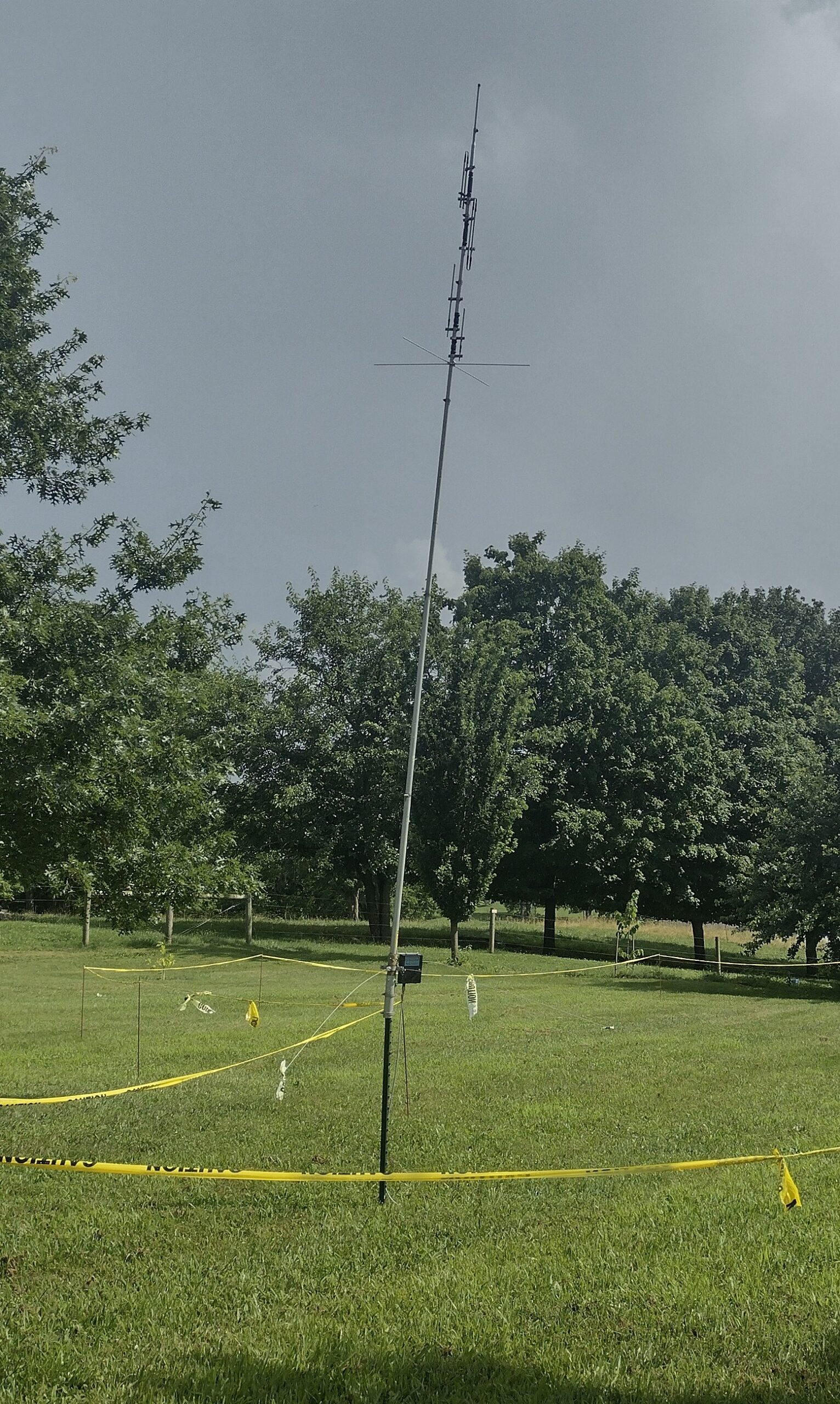
A Cushcraft R5 vertical with included elevated counterpoise wires supporting 20-17-15-12-10 is shown in the photo. Verticals are used in one antenna cluster to provide cross-polarization isolation with another cluster using Yagi’s and inverted vees. The R5 is supported on a 5 or 6 feet T-post driven into the ground. The R5 has been out of production for a number of years and Cushcraft produced the R6000 instead, but it is also now out of production. T-posts can be easily driven with a T-post driver and then removed with a T-post puller. A T-post is very sturdy also. We also use T-posts for the element end supports for 80-40 inverted vees and also for securing guy ropes. By using T-posts for a number of support functions, efficiency results. Their usage does require permission to temporarily drive posts and to have fields, lawns, shoulder areas,… for setup. Also, any underground utilities that may be shallow in depth needs to be considered.
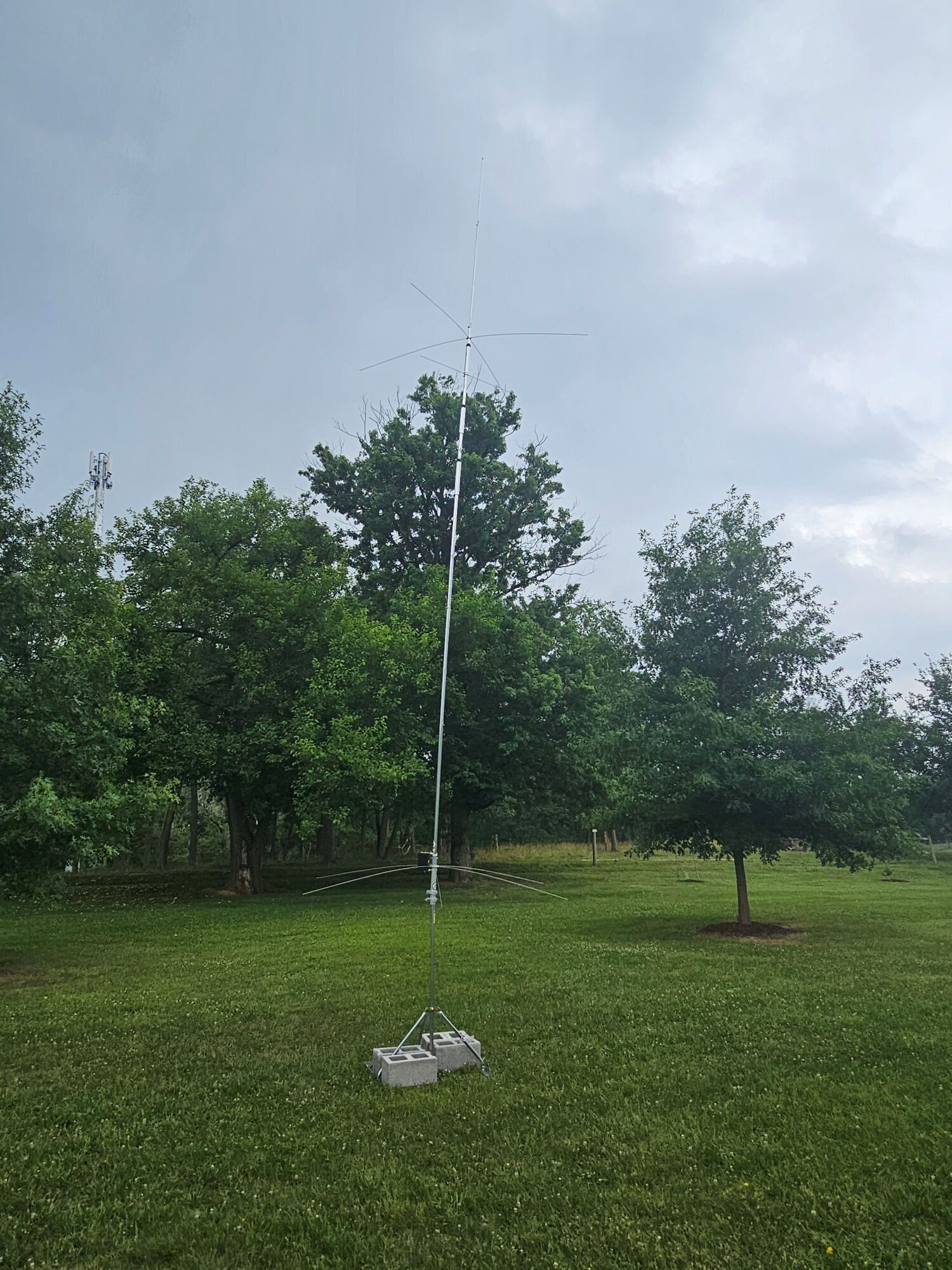
In the picture a Chelegance KC4 40-20-15-10 vertical which is in production as of 2026. This was used at Field Day 2026 to support CW for 20-15-10 (40 was unused on this antenna). The antenna avoids ground driven posts in this setup and uses an EZ NP-60-125 antenna mount. Weights secure it.
80-40 Meter Antennas
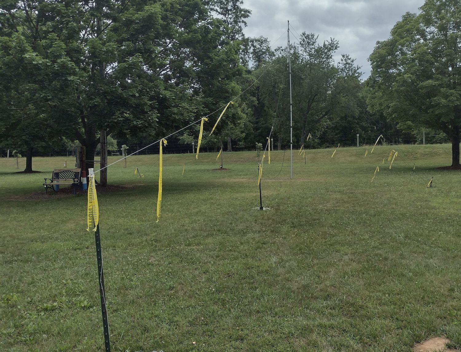
This is a picture of an 80-40 widespaced inverted vee setup.
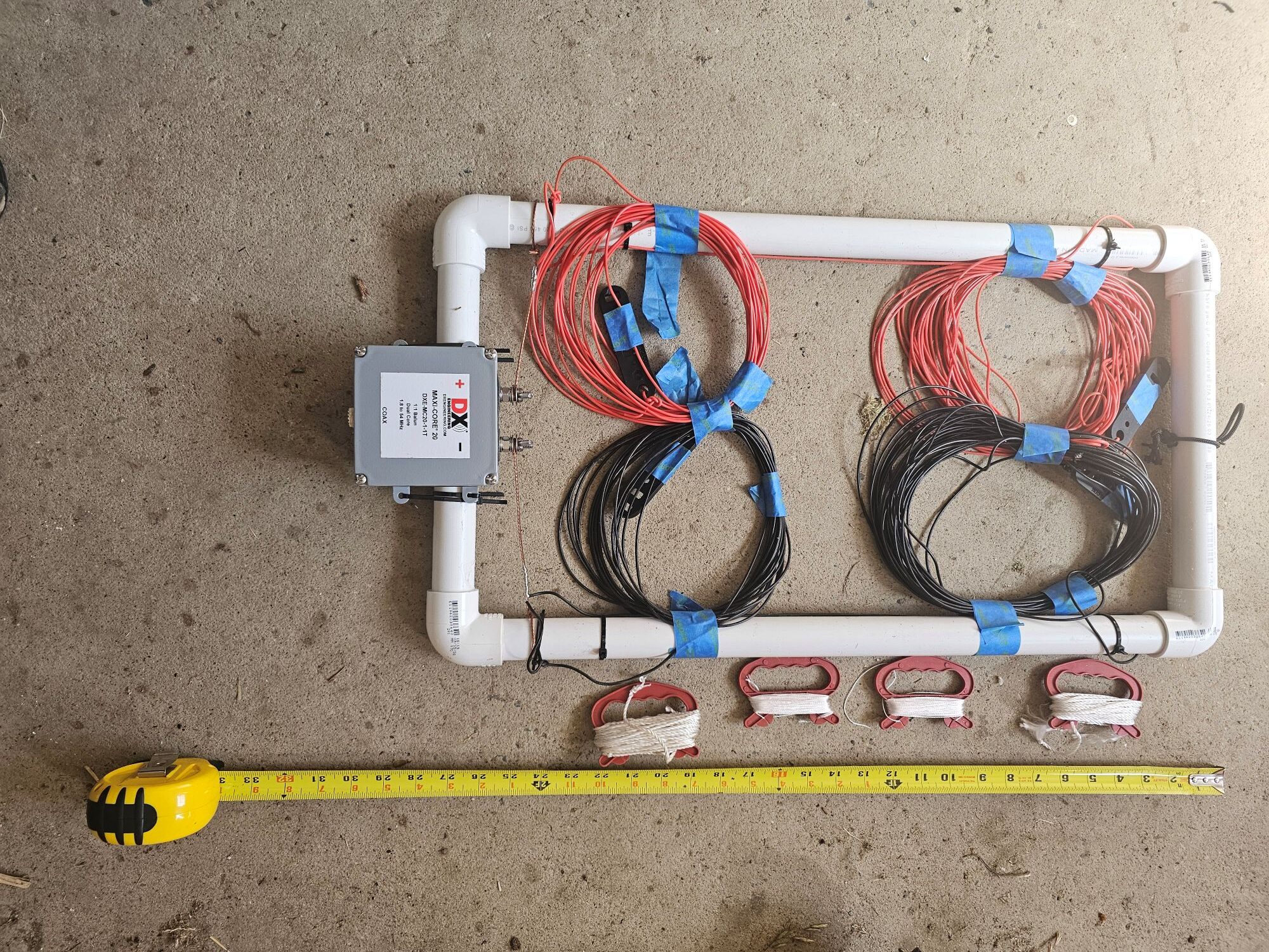
This is the 80-40 inverted vee torn down excluding the fiberglass mast, guy ropes, T-posts,… The 80-40 inverted vee shares a coax to connect to the 80-40-(20) triplexer. The 1″ PVC spacer in the center separates the 80 and 40 meter legs by about 2 feet vertically at the center. The 4 element wires then connect with ropes that go to 4 separate T-posts with the 80 and 40 meter elements spreading to increasing separation. It is possible to move each element leg individually which allows to optimizing isolation between the inverted vee and other antenna clusters, especially for the verticals used for CW.
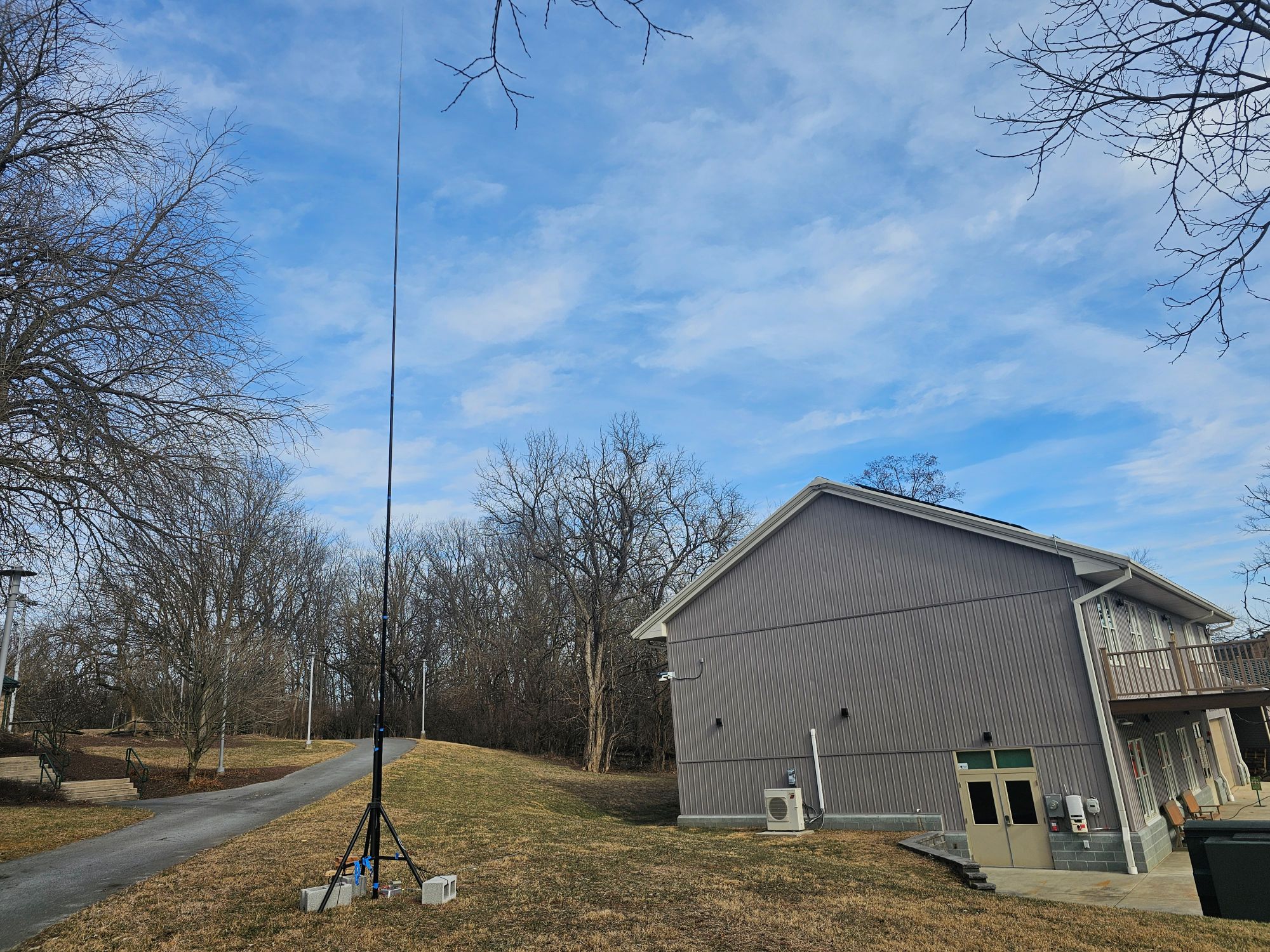
The 80-40 vertical is shown in this picture. In this case, a surplus tripod is used with weights on each leg.
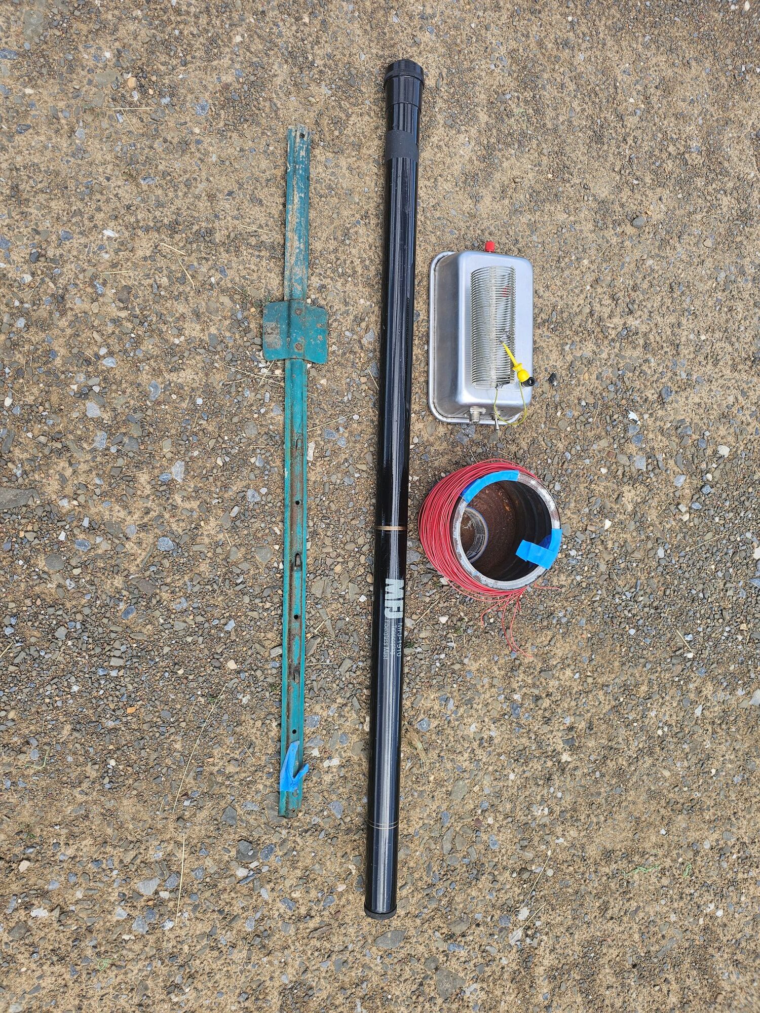
This picture shows the components for the 80-40 antenna using a ground driven post instead of a tripod. There are eight 33 feet radials laying on the ground using insulated hookup wire (#18 is good). A 33 feet fiberglass pole is used to support a single vertical wire with the wire taped to the pole using painters tape (there are 9 wires in total of 33 feet in length – the vertical driver wire may be slightly different after tuning. A matchbox was built in a baking pan upside down. The coil on top provides loading on 80 meters to resonant the antenna on 80 meters. The red binding post goes to the vertical element and the black binding post goes to the 8 radials. A heavy duty toggle switch DPDT changes the antenna from 40 to 80 meters. One toggle switch pole shorts out or bypasses the loading coil on 40 meters. The other toggle switch pole selects the direct RF input on 40 meters where the impedance is close to 50 Ohms, and it selects the output of an RF transfomer using an FT240-43 core with 8 primary turns and 5 secondary turns (this could also be an UNUN of appropriate design) where the impedance may be 15 to 20 Ohms.
Other Antennas
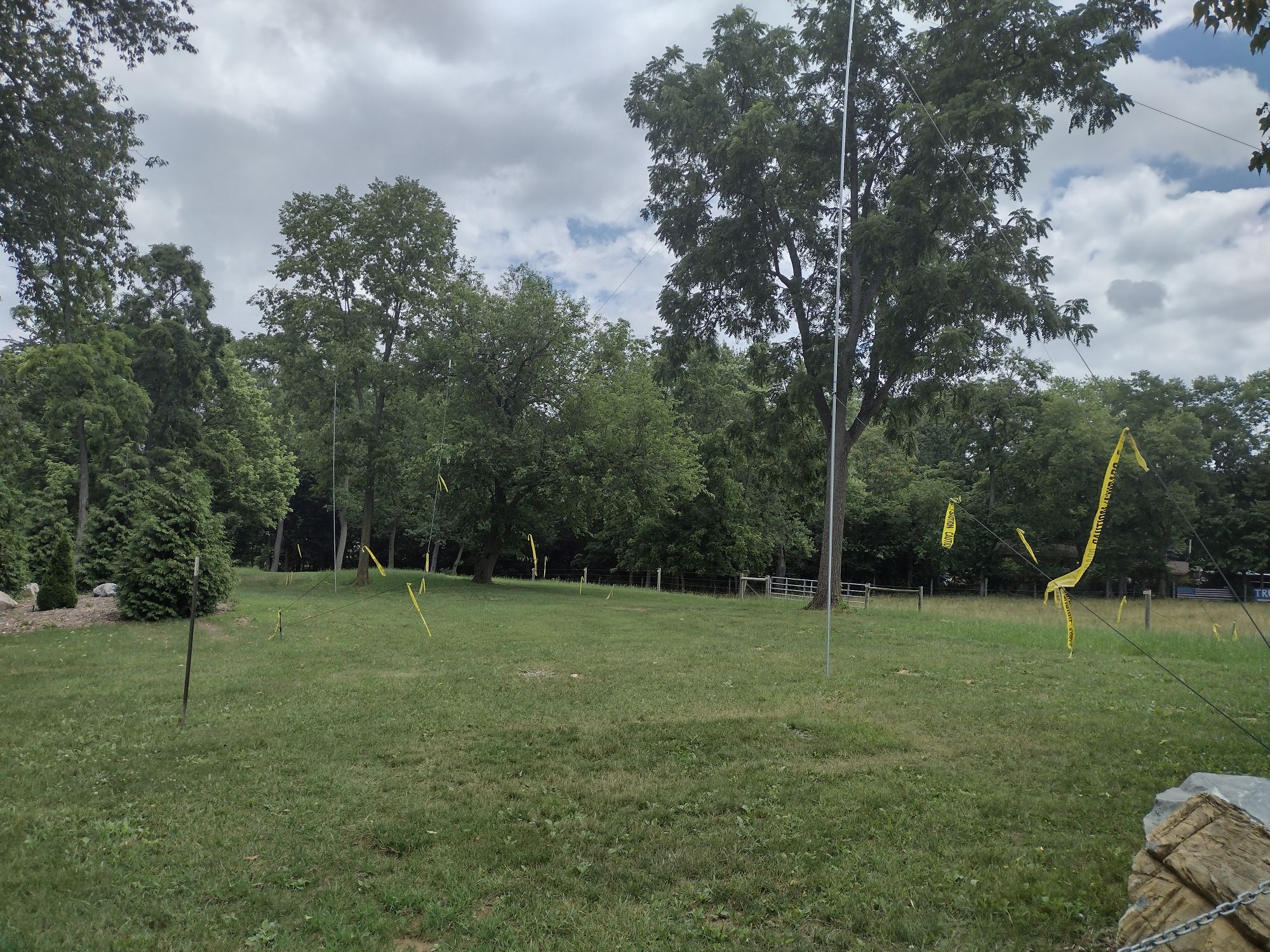
This picture shows a 5-band trap dipole 80-40-20-15-10 that we have used some years for a 3rd cluster in cross polarization, for a digital rig. No TFS was used and a single rig was supported. Inexpensive 10 feet steel fence top rail are used for the two masts. The rail pieces are tapered at one end to fit together. We sloped the dipole slightly to optimize cross-polarization isolation with a Yagi and inverted vee cluster and a vertical cluster based on EZNEC modeling due to coupling with a combination of near and far field and ground reflection components. with the closer end at 30 feet and the far end at about 27 feet. Two sets of guy ropes are needed. T-posts were used to secure the guy ropes. The masts can be raised safely and quickly by 5 hams with one on each set of guy ropes, one walking up the mast and one securing the base. The design is based on http://degood.org/coaxtrap/. The traps are coaxial traps which we constructed based on the published designs.
The trap dipole was tuned for digital/CW operation near the bottoms of each band. Trap antennas are not recommended for 80 and 40 meters for phone operations for Field Day due to the reduction in SWR bandwidth for the low bands with trap-based antennas. But for digital/CW this is not a significant issue.
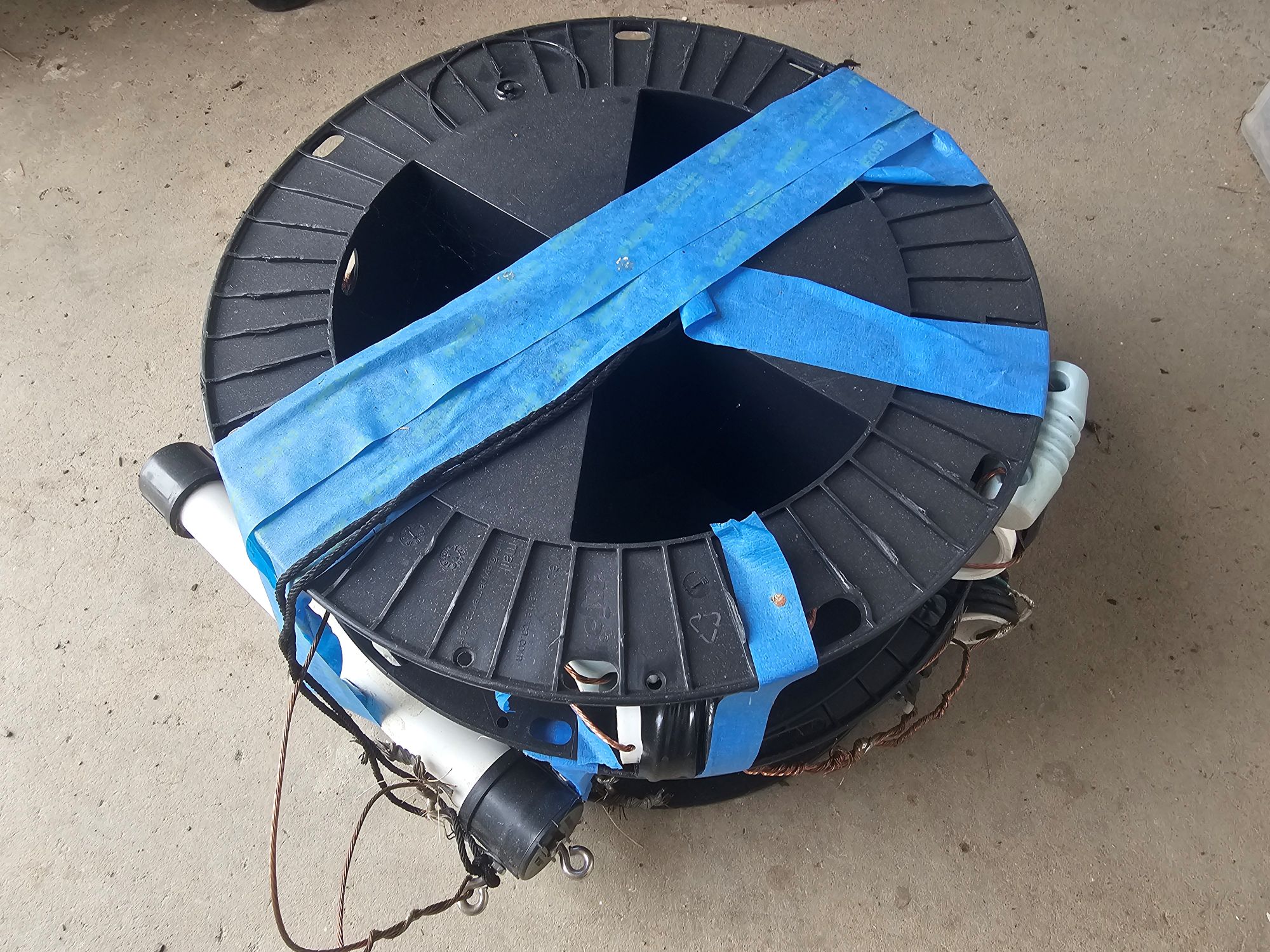
The trap 5-band 80-40-20-15-10 antenna is rolled up on two large plastic spools, one for each side of the antenna in the picture. Several coaxial traps can be seen constructed on PVC pipe parts and a center BALUN is to the lower left.. The trap antenna worked well for a single digital rig and would also be fine for a single CW rig with operations across the 5 bands. Since it is a straight line dipole, placing it in cross-polarization or end-to-end orientation for same-band isolation is feasible.
There are a number of multi-band wire antenna options which can be considered for Field Day. These include EFHW dipoles, OCF dipoles, G5RV, Carolina Windom, Zepp, extended double Zepp and others, Depending on the setup for a club, one or more of these may be attractive. But we have avoided wire antennas that do not have separate elements or traps for each band to allow optimizing the operating frequency independently on each band. If the resonant frequency can not be independently tuned for each band, the ability to operate with a TFS will generally be compromised and operating the TFS with low SWR and a well matched system may be a problem. Placing a tuner on the antenna side of a TFS generally does not work since tuners are designed to support 1 frequency or band at a time. Some of these antennas may have a combination of vertical and horizontal radiation which can limit the usage of end-to-end, side-to-side and cross-polarization isolation techniques. A Carolina Windom has explicit vertical and horizontal sections and is likely to be problematic for a setup designed for same-band multi-rig operations. G5RV and Zepp’s generally require antenna tuners. EFHW and OCF dipoles have complex antenna patterns on the higher frequency bands which can complicate isolation. For 1 to 3 rig setups and/or for setups with NO same-band operations or no TFS operations, these antennas can be attractive since setup can be fairly easy. There is at least one club located in the USA interior that uses several extended double Zepp antennas very successfully to provide multiband operation and double sided antenna patterns to reach both the east and west coasts, but tuners are needed and no TFS operation is used. If multi-rig operations and especially same-band operations are intended, modelling the setup with EZNEC for isolation and performance is recommended.
The strength of TX signals and directionality can be an important factor for clubs and may depend on club location. East coast operations may prefer Yagi’s or directional antennas for 20-15-10 and even 40 pointing west and setup side-to-side, while west coast operations may prefer Yagi’s pointing east. Texas and Florida operations may point antennas appropriately. There is generally limited to no rotation of directional antennas during operating due to the time required for rotations. Clubs operating in the interior of the USA may use dipoles or other antennas with major lobes pointing both east and west. Some antennas allow switching of director and reflector operations electrically and nearly instantaneously which may be attractive for interior operations.
Some clubs have decided against the usage of verticals due to the short to mid range of many Field Day contacts where low-angle DX antenna patterns of verticals may not be helpful and the lack of strong near vertical signals may a factor. The ARA uses inverted vees on 80/40 and Yagis at 35 to 40 feet on 20-15-10 for phone and sometimes digital operations to give phone operations an advantage for strong near vertical signals. For CW, verticals are used to support excellent isolation with fairly close inverted vees and Yagis between phone and CW for same-band operations, and for very easy setup with limited equipment. Any disadvantage for lack of near vertical signals is less important for CW than for voice while strong low angle signals may be helpful to reach the west coast from the east coast on CW. For excellent isolation between 3 clusters of antennas for digital, phone and CW for operations with same-band interference, the ARA sometimes uses a 5-band trap dipole for digital in cross polarization with an inverted vee and Yagi for phone and also in cross polarization with verticals. To actually achieve cross-polarization, the 3 clusters must be placed along a single line with the 5-band dipole aligned with the center of the inverted vee, and the verticals aligned also with the center of the inverted vee but on the opposite side from the 5-band dipole. This also ensures cross-polarization between the 5-band dipole and the verticals. See: Field Day Interference.
Useful web sites:
https://www.kkn.net/dayton2009/W3AO_2009.pdf
https://www.kkn.net/dayton2009/Dayton_FD_W2RDX.pdf
https://bvarc.org/Tech/2022CuriousConfluence.pdf
Thanks to the Antietam Radio Association (ARA) for effort, support and funding of Field Day antennas, TFS’s, laptops, and other equipment. And thanks to club members for providing light towers, other antennas, coaxes, and other equipment.
Thanks to Washington County Division of Emergency Services for providing equipment, including rigs, access and usage of the EmComm trailer, and funding for antennas.